
If you like anything, buy it. Desire is easy to satisfy. But when what you want to get does not exist, you may need to use your obsession with your ideals.
In the childhood’s vague memory, a well-organized hole plate in the father’s toolbox, let me now have the idea of making a PS4 wireless arcade joystick that I have never even seen before. In the childhood of the game room, pay tribute to my most respected old father.
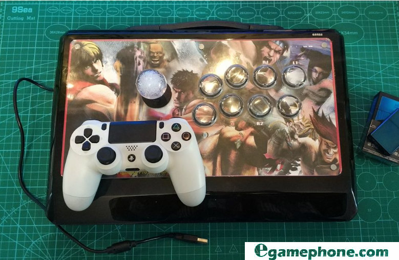
This is a PS3 joystick that I bought for a few years ago to play Street Fighter 4 on PS3. I have customized the Sanhe button of the water-clearing rod, which is my own habit. The USB connection PC can also be used as a PC joystick. However, it cannot be recognized on the PS4.
The controller is bundled with the PS4 SLIM mainframe. This is the last one.
The old frame of the blockboard has been a long time, but the weight and the line are still quite solid.
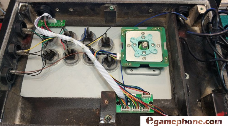
In addition to the four-wire one ground of the standard 5pin plug, the other buttons use a common single line, not a standard 2pin plug. The board and the line must be replaced.


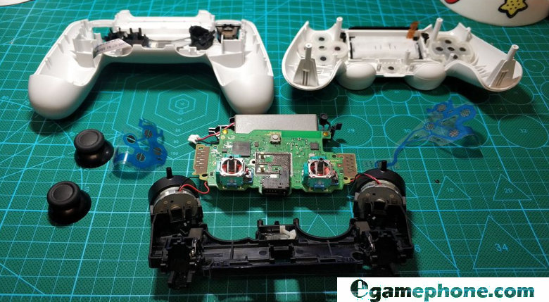
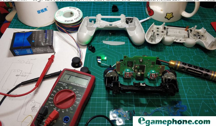
If you are not afraid to die and do it, remember that before you open your baby PS4 handle, you must first pair it with Bluetooth and the computer, and correctly recognize the handle on the computer. This step is very important! Because in the process of flying wire and welding in the back, it is necessary to constantly energize the test button to connect correctly and normally conduct. Removing the handle is probably the easiest step in the whole modification process. Anyway, it will dig the motherboard with the authorized chip out, so it is very rough, very violent, very casual, very enjoyable.
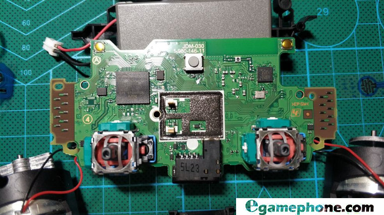
I have seen some modification tutorials before, but it is a bit of a slap in the face to see the board. This TM is different from all the boards that I have seen online before.
After forcibly calming down, determine the idea, use the film on the handle button to find the corresponding contact of each button on the main board, lead the flying line, and give the joystick button.
The PS4 handle is changed to the arcade joystick. In the end, it is the two biggest difficulties:
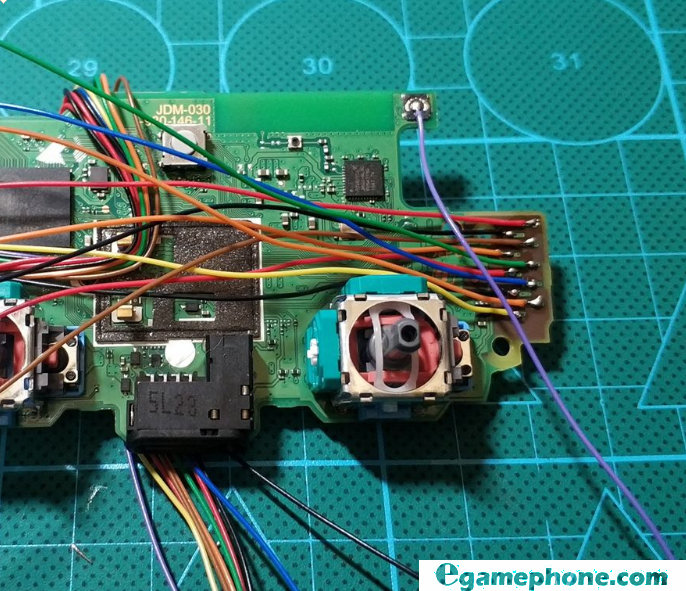
First, how to correctly find the corresponding contact of the button, the version of the handle is varied, basically a revision, the online map is wrong, I believe that after reading this post, if you remove the handle, the points you see will be different.
Here to teach you a way to do not rely on online tutorials, find your own way: the printed circuit on the button film, can help us find the right point, just follow the printed circuit line, find each button corresponding to the handle on the motherboard The contacts are all right. Each button has two access points on the film, one of which is the intercommunication of multiple buttons, which is the ground point (GND), and the other end is the signal input of the corresponding button. Except for L1, L2, R1, and R2, all the buttons use the same grounding point, except that the GND is made on the left and right sides of the handle circuit board. In fact, the two GNDs can be common ground, that is, as long as they are connected. A GND to the joystick is fine. The same is true for SHARE and OPTIONS.
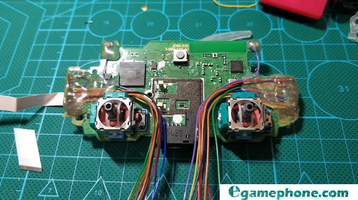
More particular are L1 and L2, R1 and R2. These four buttons are considered to be essentially common ground, but I still gave them two separate flying leads for each button, because the actual measurement of the film, the L2 and R2 breakpoints (that is, the buttons) must be connected in parallel. A 6.35K resistor. A 7.55 resistor should be connected in parallel between L and R. If you ignore these resistors, there will be a phenomenon in which L and R are inexplicably triggered when there is no button.
Remember to prepare a piece of paper and a pen to record the points you found. My mind is so good. It still feels a bit difficult to remember 20 points. Moreover, it is cool to make a mistake, so this process is forced.
After finding all the points, the second difficulty is how to accurately solder the flying leads to the board. If you are not very experienced in soldering small connectors, it is not recommended to try it easily. 20 printed circuit board contacts with a pitch of less than 1mm are brittle. If it is not a knife flow, basically this solder joint will collapse. If you are quite confident in your own craftsmanship, are courageous enough, and have the consciousness of destroying an original handle, you can start flying.
First of all, you need a reliable, well-grounded soldering iron. Of course, if the condition is good, the soldering station is the best. This can avoid the welding process, because the induced current breaks through the handle IC, and the temperature-controlled soldering iron or soldering station can be accurate. Control the soldering temperature. In general, the tip setting temperature is preferably 60-80 degrees higher than the melting point of the solder wire used.
There is a key point to note that the contacts on the handle board are coated with a similarly solidified toner. Remember to use a 5000-mesh fine sandpaper or blade to remove the copper sheet that exposes the board, otherwise it will be soldered. The board is peeled, the contacts are broken, the chip is on fire, and it is not soldered.
When I first flew SHARE and OPTION, I wanted to pick it up from the solder joint on the edge of the reed button, but the solder joint was too small to be soldered. So after the reed was smashed, it was directly soldered. In the middle, very comfortable.
If the hands are cooked, use the finest tip to control the temperature, basically no need to use rosin and flux. This process is very time consuming, it takes about 5 hours to find all the 20 points from the point of finding, and check if the solder joints are correct during the process.
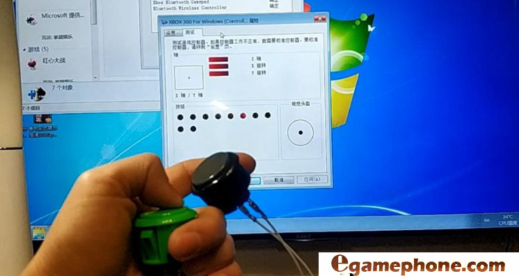
After all the flying leads are soldered, test each button on the computer to see if it works normally. Remember to pair with the computer before the handle is removed. If you want to pair at this time, you need to connect SHARE. HOME, and GND open the handle, it will be very troublesome, don’t ask me how I know. Because the L2 and R2 are not connected in parallel at this time, the Z axis will jump when testing, which is normal.
Then the solder joint can be sealed with hot melt adhesive. After hot melt adhesive, you can no longer change the fly line to receive electricity. You must be careful before doing this step.
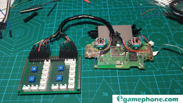
The adapter board to be done next is out of my own waywardness. I want to make an adapter board, use a standard 2pin socket, and the flying line is also made into a quick release specification with DuPont. In case the handle board is smashed, or if there is a PS5 handle in the future, I don’t need to re-weld the line at the end of the rocker. Just remove one handle, release the flying line, and solder the DuPont head to replace the handle board directly. It can even be replaced with an XBOXONE controller or other IC’s handle motherboard.
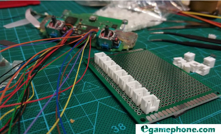
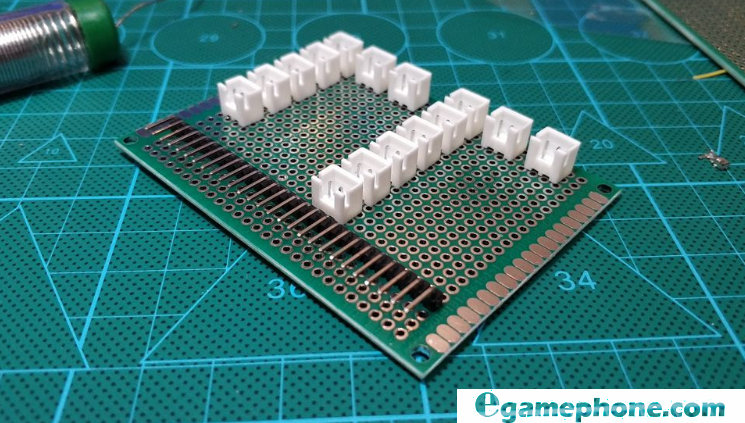
Used 2.25mm double-sided experimental board, commonly known as hole board. Standard parts are used for both 2pin sockets and sockets. The layout of the socket position still needs to be thought of, and it is necessary to conform to the habit of plugging in. The back is convenient for routing, but also looks beautiful, so before and after welding, the layout has been changed several times before and after, and finally it is this layout. .
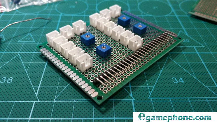
L, R button resistance, I used a potentiometer on hand, in fact, is a 0-10K varistor. The multimeter is adjusted to the required resistance value, and it is also installed on the adapter board, so that it is convenient to change the other handles of the motherboard for debugging.
If the trace on the back of the adapter board is really expensive, it will take a lot of time and effort. When I walked through the ground, I gave up the way of wiring that I wanted to make a printed circuit board. Gated.


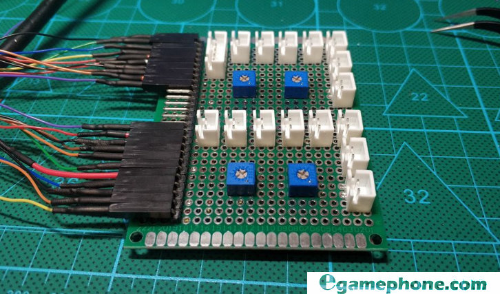
DuPont heads are made for the flying line. Each flying line is reinforced with heat-shrink tubing, and a patch panel that looks like a decent image is completed. This step has taken more than 10 hours.
Use the tweezers to short-circuit the HOME button of the 2pin socket, and test the buttons one by one on the computer. At this time, there is no L2 and R2 jumping, and the parallel resistance is really fragrant.
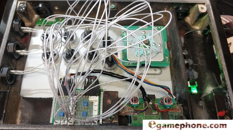
Then there is the step of finishing the flying line, without any technical content.
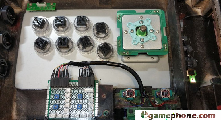
Remove the old wire in the frame and cut the screw column from the handle housing to fix it on the frame. The self-tapping screws of the wooden frame frame can be easily disassembled in the future.
I plugged a TYPEC to standard USB female adapter cable on the USB cable port on the handle to facilitate wired connection and charging. Here you can see your personal preferences. As long as you have a fixed place, you can stand up to the USB cable repeatedly.
Replace the button wire of the 2pin standard plug. It’s like a time bomb.
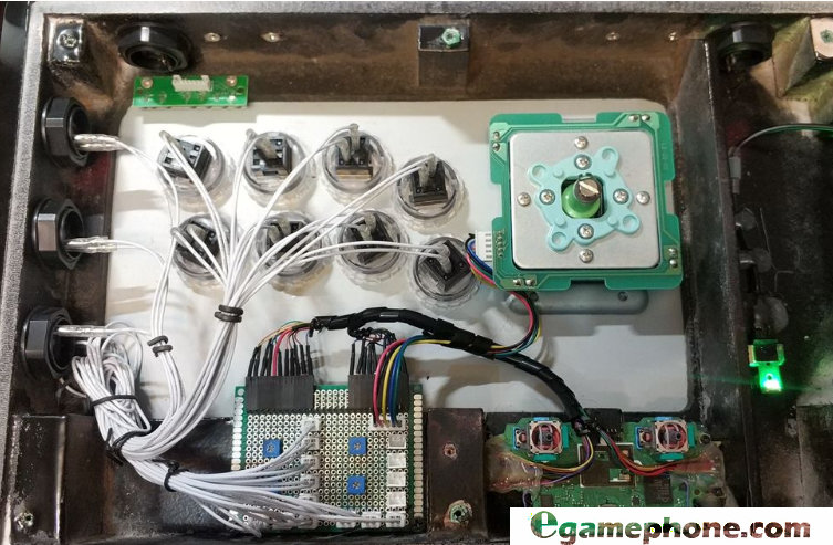

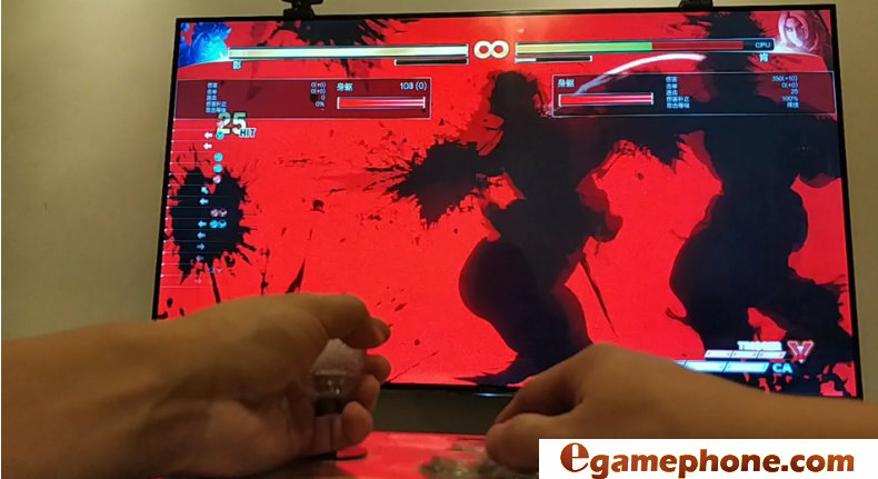
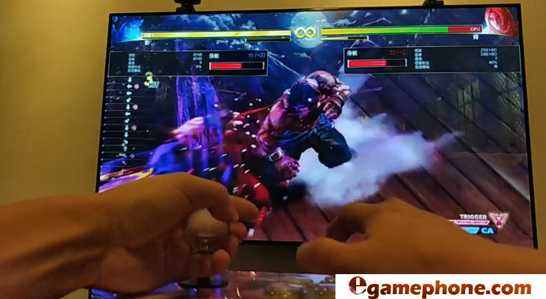
USB connection PS4 boot pairing, then unplug the USB, the wireless PS4 joystick is completed.
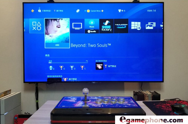
No delay, no dropped calls, no need for genuine PS4 handle boot (my TM only genuine handle has been removed
The article was originally created by egamephone.com. If reproduced, please indicate source.
Egamephone.com focuses on the maintenance, upgrade and transformation of various models of playstation, xbox, nintendo and gameboy. If you are a fan, please join us at http://egamephone.com/!
Facebook:https://www.facebook.com/kasynhk/
Twitter: https://twitter.com/PlayStation4_pr
Pinterest: https://www.pinterest.com/topgamearena/
Instagram: https://www.instagram.com/egamephone/
